Kia Cadenza YG: Front Axle Assembly / Front Hub - Axle Repair procedures
Kia Cadenza YG 2016-2021 Service Manual / Driveshaft and axle / Front Axle Assembly / Front Hub - Axle Repair procedures
| Replacement |
| 1. |
Loosen the wheel nuts slightly.
Raise the vehicle, and make sure it is securely supported. |
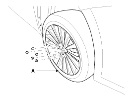
| 2. |
Remove the front wheel and tire (A) from front hub.
|

| 3. |
Remove the brake caliper mounting bolts , and then place the brake caliper assembly (B) with wire.
|

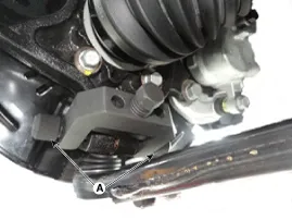
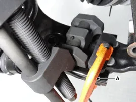
| 4. |
Remove the tie rod end ball joint (A) from the knuckle.
|

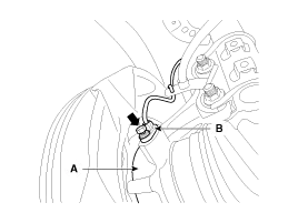
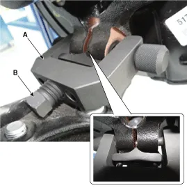
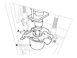
| 5. |
Loosen the mount bolt and then remove the wheel speed sensor (B) from knuckle (A).
|
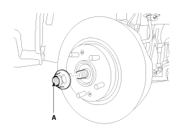
| 6. |
Remove driveshaft caulking nut (A) from the front hub under applying the break.
|

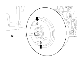
| 7. |
Loosen the front brake disc mount screw and then remove the front brake disc (A).
|
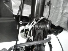
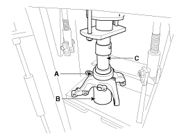
| 8. |
Remove the lower arm (A) from the knuckle.
|

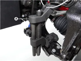
| 9. |
Remove the front lower arm from the front knuckle using the SST (0K545-A9100).
|


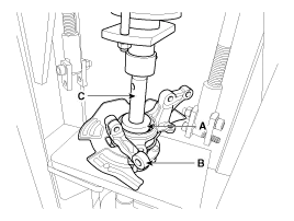
| 10. |
Disconnect the driveshaft (A) from the front hub assembly and
then loosen the strut mount bolts and then remove the knuckle assembly
(B).
|

| 11. |
Install in the reverse order of removal. |
| Inspection |
| 1. |
Check the hub for cracks and the splines for wear. |
| 2. |
Check the brake disc for scoring and damage. |
| 3. |
Check the knuckle for cracks. |
| 4. |
Check the bearing for cracks or damage. |
| Disassembly |
| 1. |
Remove the snap ring (A).
|

| 2. |
Remove the hub assembly from the knuckle assembly.
|
| 3. |
Remove the hub bearing inner race from the hub assembly.
|

| 4. |
Remove the hub bearing outer race from the knuckle assembly.
|
| 5. |
Replace hub bearing with a new one. |
| Reassembly |
| 1. |
Install the hub bearing to the knuckle assembly.
|

| 2. |
Install the hub assembly to the knuckle assembly.
|
| 3. |
Install the snap ring (A).
|
Components 1. Coking nut2. Brake disc3. Hub4. Dust cover5. Knuckle6. Wheel bearing7. Snap ring8. Drive shaft
Other information:
Kia Cadenza YG 2016-2021 Service Manual: Adaptive Front Lighting System Repair procedures
Removal 1. Disconnect the negative (-) battery terminal. 2. Using a screwdriver or remover, remove the crash pad side cover (A). [RH] 3. Disconnect the stopper (B) from the glove box (A). 4. Disconnect the air damper (A) from the glove box (B).
Kia Cadenza YG 2016-2021 Service Manual: Cluster ionizer Repair procedures
Inspection 1. Press the OFF switch more then 4 times within 2 seconds while pressing the MODE switch. DisplayFail description00Normal50Cluster ionizer fault * Diagnostic procedure refer to DTC code. Replacement 1. Disconnect the negative (-) battery terminal.
Categories
- Manuals Home
- Kia Cadenza Owners Manual
- Kia Cadenza Service Manual
- Body (Interior and Exterior)
- Engine Electrical System
- Engine Mechanical System
- New on site
- Most important about car

Copyright © 2026 www.kcadenzavg.com - 0.0204