
Kia Cadenza YG: Engine Control System / Barometric Pressure Sensor (BPS) Schematic Diagrams
| Circuit Diagram |
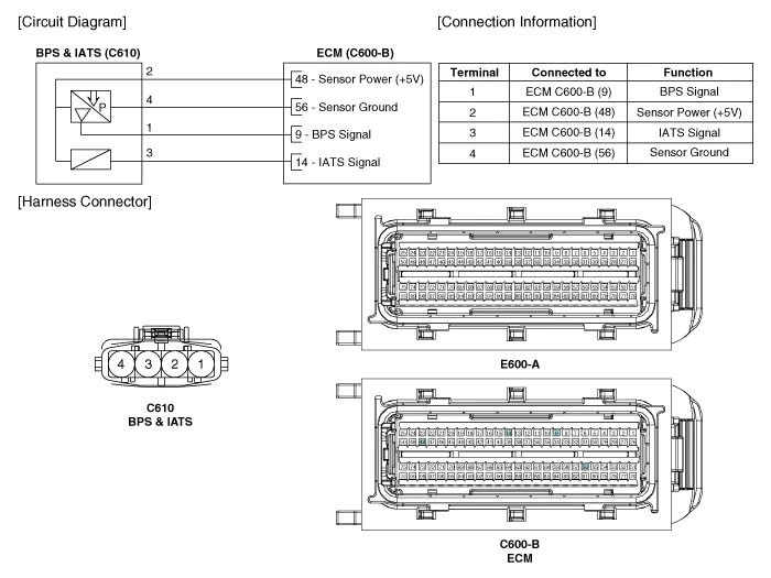
Specification Pressure [kPa (kgf/cm², psi)]Output Voltage (V)10.0 (0.01, 0.15)0.5055.0 (0.56, 7.98)2.21115.0 (1.17, 16.9)4.50
Inspection 1. Connect the GDS on the Data Link Connector (DLC). 2. Measure the output voltage of the BPS at idle and IG ON. Specification: Refer to "Specification" Removal 1.
Other information:
Kia Cadenza YG 2016-2021 Service Manual: A/C Pressure Transducer Repair procedures
Inspection 1. Measure the pressure of high pressure line by measuring voltage output between NO.1 and NO.2 terminals. 2. Inspect the voltage value whether it is sufficient to be regular value or not. Voltage = 0.00878835 * Pressure + 0.37081095 [PSIA] 3.
Kia Cadenza YG 2016-2021 Service Manual: Blower Unit Components and Components Location
Component Location Components 1. Duct Seal2. Duct Case3. Inlet Door4. Intake Actuator5. Inlet Duct Case (A)6. Climate control air filter7. Cluster Ionizer8. Climate control air filter Cover9. Blower Upper Case10. Blower Lower Case11. FET12. Resistor13.
Categories
- Manuals Home
- Kia Cadenza Owners Manual
- Kia Cadenza Service Manual
- Brake System
- Suspension System
- Schematic Diagrams
- New on site
- Most important about car
