Kia Cadenza YG: Cylinder Head Assembly / CVVT & Camshaft Repair procedures
Kia Cadenza YG 2016-2021 Service Manual / Engine Mechanical System / Cylinder Head Assembly / CVVT & Camshaft Repair procedures
| Removal |
Continuous Variable Valve Timing (CVVT)
| 1. |
Remove the timing chain.
(Refer to Timing System - "Timing Chain") |
| 2. |
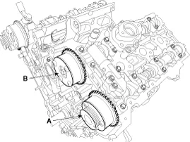
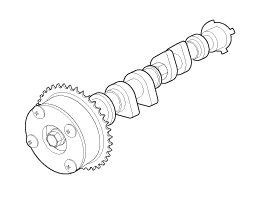
Remove the CVVT assembly.
|

Camshaft
| LH Intake and Exhaust camshaft |
| 1. |
Remove the timing chain.
(Refer to Timing System - "Timing Chain") |
| 2. |
Remove the LH exhaust camshaft oil control valve (OCV).
(Refer to Engine Control/Fuel System - "CVVT Oil Control Valve (OCV)") |
| 3. |
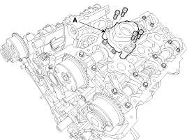
Remove the fuel pump bracket (A)
|
| 4. |
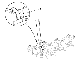
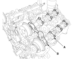
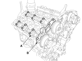
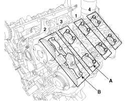
Remove the LH camshaft bearing cap (A) and thrust bearing cap (B).
|
| 5. |
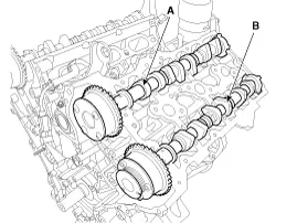
Remove the LH camshaft assembly (A).
|
| RH Intake and Exhaust camshaft |
| 1. |
Remove the timing chain.
(Refer to Timing System - "Timing Chain") |
| 2. |
Remove the RH exhaust camshaft oil control valve (OCV).
(Refer to Engine Control/Fuel System - "CVVT Oil Control Valve (OCV)") |
| 3. |
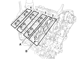
Remove the RH camshaft bearing cap (A) and thrust bearing cap (B).
|
| 4. |
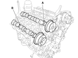
Remove the RH camshaft assembly (A).
|
| Inspection |
Continuously variable valve timing (CVVT) Assembly
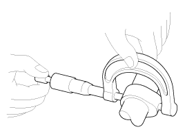
| 1. |
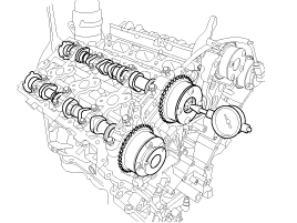
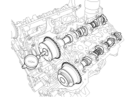
Inspect the CVVT for smooth rotation.
|

Camshaft
| 1. |
Inspect cam lobes.
Using a micrometer, measure the cam lobe height.
If the cam lobe height is less than standard, replace the camshaft. |
| 2. |
Inspect the camshaft journal clearance.
|


| 3. |
Inspect the camshaft end play.
|
| Installation |
Continuous Variable Valve Timing (CVVT)
| 1. |
Install the CVVT assembly.
|
| 2. |
Install the timing chain.
(Refer to Timing System - "Timing Chain") |
Camshaft
|
| LH Intake and Exhaust camshaft |
| 1. |
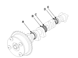
Install the LH intake camshaft (A) and exhaust camshaft (B).
LH Intake camshaft
As for camshaft identification, refer to the table below.
LH Exhaust camshaft
As for camshaft identification, refer to the table below.
| ||||||||||||||||||||||||||
| 2. |
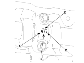
Install the bearing cap (A) and thrust bearing cap (B) with specified torque.
A : L(LH),R(RH)
B : I(Intake), None(Exhaust)
C : Journal number
D : Front mark
|
| 3. |
Install the fuel pump bracket (A)
|
| 4. |
Install the other parts reverse order of removal. |
| RH Intake and Exhaust camshaft |
| 1. |
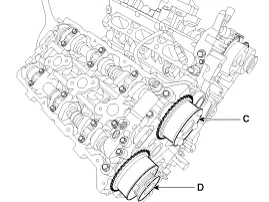
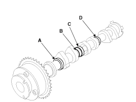
Install the RH intake camshaft (A) and exhaust camshaft (B)
RH Inkate camshaft
As for camshaft identification, refer to the table below.
RH Exhaust camshaft
As for camshaft identification, refer to the table below.
| ||||||||||||||||||||||
| 2. |
Install the bearing cap (A) and thrust bearing cap (B) with specified torque.
A : L(LH),R(RH)
B : I(Intake), None(Exhaust)
C : Journal number
D : Front mark
|
| 3. |
Install the other parts reverse order of removal. |
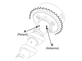
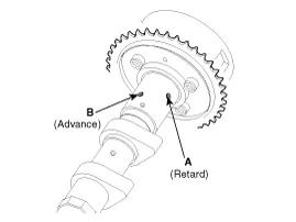
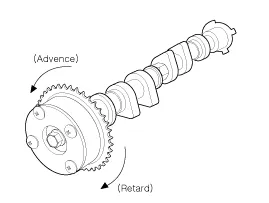
Description Continuous Variable Valve Timing (CVVT) system advances or retards the valve timing of the intake and exhaust valve in accordance with the ECM control signal which is calculated by the engine speed and load.
Components 1. RH Cylinder head2. RH Cylinder head gasket3. LH Cylinder head4. LH Cylinder head gasket5. Cylinder block 1. Camshaft bearing cap 2.
Other information:
Kia Cadenza YG 2016-2021 Service Manual: Components and Components Location
C
Kia Cadenza YG 2016-2021 Service Manual: Blind Spot Detection Variant Coding Description and Operation
Description The used radar frequency of BSD is two, "North America region" and "Except North America region". If it replaces BSD unit, BSD unit has to perform the procedure of variant coding. BSD Variant Coding 1. Select the "BSD Variant Coding" procedure in BSD system.
Categories
- Manuals Home
- Kia Cadenza Owners Manual
- Kia Cadenza Service Manual
- Engine Control / Fuel System
- Steering System
- Automatic Transaxle System
- New on site
- Most important about car

Copyright © 2026 www.kcadenzavg.com - 0.0248