Kia Cadenza YG: Automatic Transaxle Control System / Transaxle Control Module (TCM) Repair procedures
| Removal |
When replacing the TCM, the vehicle equipped with the immobilizer must be performed procedure as below.
[In the case of installing used TCM]
[In the case of installing new TCM]
Perform "Key teaching" procedure with GDS.
(Refer to Body Electrical System - "Immobilizer System") |

When replacing the TCM, the vehicle equipped with the smart key system (Button start) must be performed procedure as below.
[In the case of installing used TCM]
[In the case of installing new TCM]
Insert the key (or press the start button) and turn it to the
IGN ON and OFF position. Then the TCM learns the smart key information
automatically. |
| 1. |
Turn ignition switch OFF and disconnect the negative (-) battery cable. |
| 2. |
Remove the battery.
(Refer to Engine Electrical System - "Battery") |
| 3. |
Remove the air cleaner assembly.
(Refer to Engine Mechanical System - "Air Cleaner") |
| 4. |
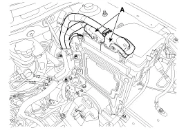
Disconnect the TCM Connector (A).
|
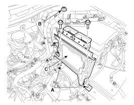
| 5. |
Remove the mounting bolts (A) and nut (B), and then remove the TCM (C).
|
| Installation |
When replacing the TCM, the vehicle equipped with the immobilizer must be performed procedure as below.
[In the case of installing used TCM]
[In the case of installing new TCM]
Perform "Key teaching" procedure with GDS.
(Refer to Body Electrical System - "Immobilizer System") |
When replacing the TCM, the vehicle equipped with the smart key system (Button start) must be performed procedure as below.
[In the case of installing used TCM]
[In the case of installing new TCM]
Insert the key (or press the start button) and turn it to the
IGN ON and OFF position. Then the TCM learns the smart key information
automatically. |
| 1. |
Install in the reverse order of removal.
|
| 1. |
TEST TCM GROUND CIRCUIT: Measure resistance between TCM and
chassis ground using the backside of TCM harness connector as TCM side
check point. If the problem is found, repair it.
|
| 2. |
TEST TCM CONNECTOR: Disconnect the TCM connector and visually
check the ground terminals on TCM side and harness side for bent pins
or poor contact pressure. If the problem is found, repair it. |
| 3. |
If problem is not found in Step 1 and 2, the TCM could be
faulty. If so, make sure there were no DTC''s before swapping the TCM
with a new one, and then check the vehicle again. If DTC''s were found,
examine this first before swapping TCM. |
| 4. |
RE-TEST THE ORIGINAL TCM: Install the original TCM (may be
broken) into a known-good vehicle and check the vehicle. If the problem
occurs again, replace the original TCM with a new one. If problem does
not occur, this is intermittent problem (Refer to “Intermittent
Problem Inspection Procedure” in Basic Inspection Procedure). |
1. TCM connector and terminal function 2. TCM terminal function Connector [A] PinDescriptionPinDescription1-45Inhibitor switch signal ''S2''2-46Inhibitor switch signal ''S3''3-47Inhibitor switch signal ''S4''4-48-5-49-6-50-7-51-8-52-9-53-10CAN communication line (HIGH)54Sports mode down switch11-55-12-56-13-57-14-58-15-59-16-60-17-61-18-62-19-63-20-64-21-65-22-66-23-67-24-68-25-69-26-70-27Ignition switch71-28-72-29Sports mode up switch73-30-74-31-75-32-76-33-77-34-78 35CAN communication line Low79Sports mode Select switch36-80-37-81-38-82-39-83-40-84Shift lock solenoid41-85Reverse lamp relay42-86P/N relay43-87-44Inhibitor switch signal ''S1''88- Connector [B] PinDescriptionPinDescription1Overdrive clutch control solenoid valve (VFS)52Underdrive brake control solenoid valve (VFS)3Input speed sensor signal53SS-B Solenoid valve (ON/OFF)4Output speed sensor signal54Output speed sensor power26Torque converter control solenoid valve (VFS)55Oil temperature sensor (-)2735R Clutch control solenoid valve (VFS)57Oil temperature sensor (+)28SS-A Solenoid valve (ON/OFF) 76Solenoid valve power 129Input speed sensor power77Solenoid valve power 251Line pressure control solenoid valve (VFS)7826 Brake control solenoid valve (VFS) 3.
Description Transaxle oil temperature sensor monitors the automatic transaxle fluid''s temperature and conveys the readings to TCM. It is an Negative Thermal Coefficient(NTC) sensor whose resistance has an inversely proportional relationship with the temperature level.
Categories
- Manuals Home
- Kia Picanto Owners Manual
- Kia Picanto Service Manual
- Fluid Components and Components Location
- Timing Chain Components and Components Location
- Driveshaft and axle
- New on site
- Most important about car