Kia Cadenza YG: Auto Lighting Control System / Schematic Diagrams
| Circuit Diagram |
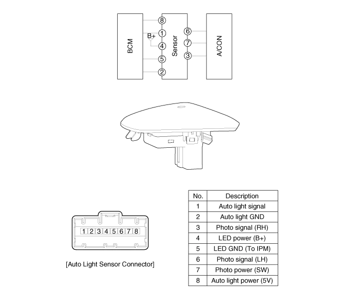
Component Location 1. Auto light sensor2. Head lamps3. Lighting switch (Auto)4. Tail lamps5. IPM (Intelligent intergrated Platform Module)
Inspection Lighting Switch Inspection With the multi function switch in each position, make sure that continuity exists between the terminals below.
Other information:
Kia Cadenza YG 2016-2021 Service Manual: Auto Head lamp leveling Unit Repair procedures
Removal Height Sensor 1. Remove the height sensor connector (A). 2. Loosen the mounting bolts(Body: 2EA, chassis: 1EA) from height sensor bracket. Tightening torque : 3 ~ 5N.m (30 ~ 50kgf.m, 2.21 ~ 3.68lb-ft) 3. Remove the height sensor.
Kia Cadenza YG 2016-2021 Service Manual: Immobilizer Control Unit Repair procedures
Removal 1. Disconnect the negative (-) battery terminal. 2. Remove the crash pad lower panel. (Refer to Body - "Crash Pad") 3. Disconnect the 5P connector of the SMARTRA unit and then remove the SMARTRA unit (A) after loosening the bolt. Installation 1.
Categories
- Manuals Home
- Kia Cadenza Owners Manual
- Kia Cadenza Service Manual
- Emission Control System
- General Information
- Rail Pressure Sensor (RPS) Schematic Diagrams
- New on site
- Most important about car
