Kia Cadenza YG: Seat Electrical / Power Seat Control Switch Schematic Diagrams
| Circuit Diagram |
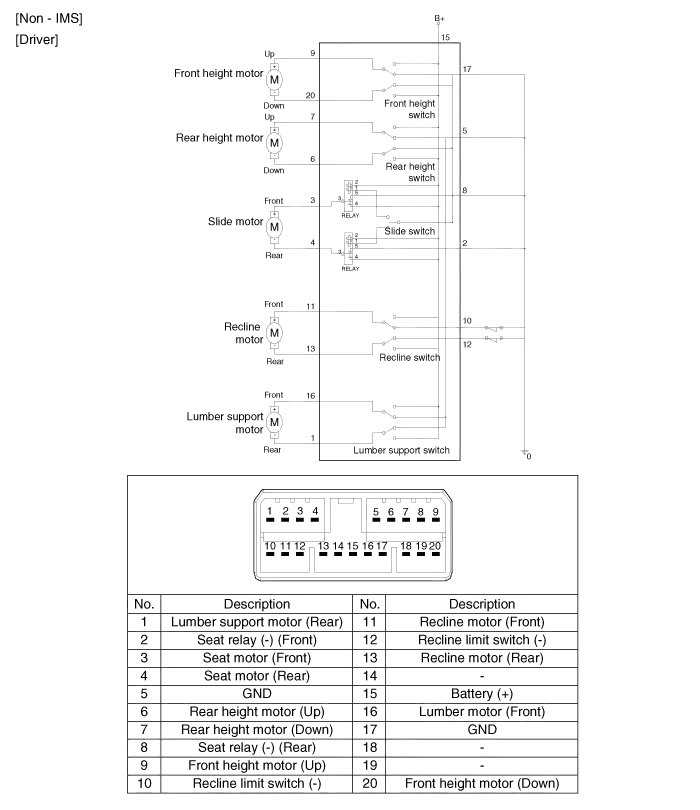
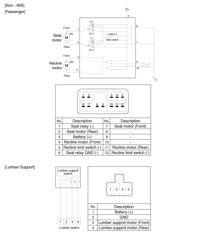
Inspection Power Seat Motor 1. Disconnect the connectors for each motor. A : Front height motor B : Slide motor C : Rear height motor D : Recline motor E : Lumber support motor F : Cushion extension motor 2.
Inspection With the power seat switch in each position, make sure that continuity exists between the terminals below. If continuity is not as specified, replace the power seat switch.
Other information:
Kia Cadenza YG 2016-2021 Service Manual: Components and Components Location
Component Location 1. Start Stop Button(SSB)2. FOB key3. RF receiver4. Smart key unit5. Interior antenna 16. Interior antenna 2 7. Trunk antenna8. Bumper antenna9. Door handle & door antenna10. Trunk lid open switch11.
Kia Cadenza YG 2016-2021 Service Manual: Blind Spot Detection Unit Repair procedures
Removal 1. Disconnect the negative (-) battery terminal. 2. Remove the rear bumper. (Refer to Body - "Rear Bumper") 3. Remove the BSD unit (A) after loosening the mounting screws. Take care not to separate the bracket from rear bumper when removing the BSD sensor.
Categories
- Manuals Home
- Kia Cadenza Owners Manual
- Kia Cadenza Service Manual
- Steering System
- Engine Electrical System
- Engine Control / Fuel System
- New on site
- Most important about car
